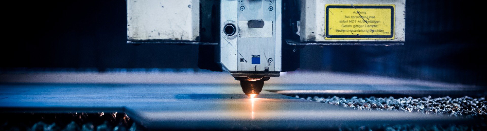

I have decided to move to FluidNC which is the successor of ESP32 GRBL which is not maintained anymore.
For this occasion, I have designed a brand new K40 FluidNC Shield which is offering much more features
This post is only applicable for Shield version v7.xx
If you want to see the post of the latest Shield version, please click here

Main upgrades :
- Use of FluidNC (GRBL ESP32 successor)
- 4 axes (to be able to manage a machine with two motors on one axis like XYYZ machines for example – 1 motor for X axis, 2 motors for Y axis and 1 motor for Z axis)
- Possibility to have an external driver fro one motor (if you need to use a NEMA23 for the Z axis for example)
- Only 1 dry contact relay instead of 2 before (the 2nd one was not used by my customers)
- Power supply stage
Enhanced & comparable features :
- Control of your machine through Wifi including Lightburn direct control over Wifi
- SDCARD to store GCODEs
- Local control via a Web interface
- Full control of the laser via Lightburn or other software using the GCODE
(movements and laser power)
The use and implementation are very similar to the previous version
Install Lightburn
Please start by installing Lightburn following my instructions
Connecting the K40 FluidNC Shield to your computer
We will start by testing the connection of the ESP32 to your PC without installing the shield in the K40.
Connect the USB cable from your PC to your ESP32
Then, under Lightburn, click on the “Console” tab in the right column. You should see something like :

Now right click on the “Devices” button in the right column.
This will restart the USB/Serial connection between Lightburn and the ESP32.
You should see indications similar to the one below on the console:

If so, your computer and laser cutter connected as intended.
Otherwise, check carefully:
- That the USB connection speed is correct (Edit/Device Settings): it should be on 115200 bauds
- That the DTR control is activated (Edit/Device Settings)
- That your USB cable is a data cable and not only and charging cable and that its length is below 80cm
It is also possible that the USB driver is not compatible with your ESP32.
You should then download and install the right version by going here :
https://www.silabs.com/developers/usb-to-uart-bridge-vcp-drivers
and choosing the CP210x Windows Drivers with Serial Enumerator version
If that still doesn’t work, it is possible that you have multiple devices on your PC that use the COM ports.
Go to your computer’s device manager (Windows key + R and enter devmgmt.msc)
Look for COM and LPT devices

Note the number of the COM port associated with the Silicon Labs CP210x driver installed just before and check that Lightburn is using the same COM port:

K40 FluidNC shield installation in your laser cutter K40
The connections are extremely simple, but be very careful to follow them carefully to avoid to damage your K40 FluidNC shield or worse your laser cutter.
You will need some female Dupont connectors for the wiring
(and the crimping tool that goes with it)
However, no need to weld anything.
Here is an overview of the FluidNC K40 shield:
- Red block : connector for the limit switches and control buttons for FluidNC (ex GRBL)
- Blue block : laser control
- Orange block : power supply for FluidNC K40 shield and stepper motors
- Yellow block : connector for the K40’s ribbon cable (if your K40 is not equipped with a ribbon cable, no problem, the K40 FluidNC shield is still compatible with your machine)
- White blocks : connectors for stepper motors

Overview of the 3 K40 classic power supplies
(if your machine uses another power supply do not hesitate to contact me, the FluidNC K40 shield will still be compatible)
Type 1 (green connectors)

Type 2 (white connectors)

Type 3 (black housing – in general for laser > 50W)

All these power supplies have a connector for the 220V mains supply (leftmost connector)
-> do not touch this connector, it must remain as it is
On the other connectors, unplug everything EXCEPT :
- The P pins and the G which is next
- Lighting and ventilation which are on the 24V pins in general. If you unplug them anyway, it doesn’t matter for the tests, you will at least have to reconnect the ventilation afterwards.
- You should therefore have completely unplugged the old main board of your K40 as well as the electronic board on the lid if your K40 has one
IMPORTANT :
To authorize a laser shot, all of these power supplies must have a closed circuit between the P and G pins for types 1 and 2 and between Water Protection and Signal Ground for type 3.
In other words, if you have a hood switch, a red laser enable button on the chassis of your laser cutter, or any other protection, these must be connected between these two pins.
As long as there is no closed circuit between these two pins, the laser will not fire.
Power supply connector (orange) on your K40 FluidNC Shield :
- Connect the “+” side to the 24V output of your power supply.
Type 3 power supplies do not have a 24V output. You’ll need a dedicated power supply. - Connect the “-” side to the G closest to the 24V on your power supply.
Laser Mngt connector (Blue) on your K40 FluidNC Shield :
- Connect the ENA pin (L) to the L input of your machine’s power supply
(for type 1 power supplies, choose the L input of the central connector) - Connect the PWM pin (IN) to the IN input of the power supply of your machine
- Connect the GND pin to the G input closest to IN on the power supply of your machine
Controls & Limits connector (Red) on your K40 FluidNC Shield :
- If you have a K40 with ribbon cable, the limit switches are already connected via this cable for the X and Y axes -> no need to connect anything to the limX and limY pins
- If your K40 does not have a ribbon cable, you will have to connect the limit switches to the LimX and LimY inputs
- If they are mechanical contactors, it is not necessary to pay attention to the wiring direction.
- If they are digital contactors (optical or capacitive), you must pay attention to the connections. The signal cable should go to the row furthest inside the board, the ground cable to the row furthest outside the board.
- If you have a motorized bed, connect the limit switch of this bed to the LimZ
- If you wish, you can wire buttons/sensors to the inputs:
- Hold: allows to pause a job (the laser is turned off, but the air assist remains active)
- Start : Allows to resume an interrupted work
- Door: If this sensor is activated, the machine will stop and the air assist will stop. Resume possible by pressing the start button
- Reset : to restart the ESP 32 and the K40 FluidNC shield
Motor connectors (white) on your K40 FluidNC Shield :
- MotX connector: if your machine is equipped with a ribbon cable, do not connect anything to this connector. Otherwise, connect the stepper motor connector of the X axis.
- MotY connector: connect the stepper motor connector of the Y axis
- MotZ connector: if you have a motorized bed, connect the connector of its stepper motor
K40 flex connector (Yellow) on your K40 FluidNC Shield :
- Lift the connector to unlock it
- Insert the ribbon cable, contacts towards the outside of the K40 FLuidNC shield
- Push the connector to lock it
Connexion example on a type 1 power supply :

Connexion example on a type 2 power supply :

IMPORTANT :
Check again all your connections and in particular the power supply connection to ensure that the polarity is correct.
Checking the end stops
We will check the 2 or 3 limit switches of the machine (2 when no motorized bed)
To do this, put the laser head in the center of the bed by hand (you must cut off the power to the machine or to enter $MD command in lightburn console to be able to move the head by hand)
Enter the command “?” in the lightburn console (without the quotes – juste the question mark sign)
The output should be something like:
<Idle | WPos: 0.000,0.000,7.700 | Bf: 31,127 | FS: 0.0>
This means that none of the limit switches are detected
If, on the contrary, you get something like :
<Idle|WPos:0.000,0.000,7.700|Bf:31,127|FS:0,0|Pn:XYZ|WCO
“Pn:XYZ” means that your limit switches are not well connected.
Check your connections in this case.
If your machine is not an original K40, it may be that your limits are not NC (normally closed) as on the original K40. In this case, contact me so I can explain how to correct this.
Once you get a response like :
<Idle|WPos:0.000,0.000,7.700|Bf:31,127|FS:0,0>
(ie without the mention Pn:….), Your end sensors are correctly configured.
We will now check that they are working well …
Put the laser head manually in the center of the X axis, and at the top stop of the Y axis (you have to cut the power to the machine or to enter $MD command in lightburn console to be able to move the head by hand).
Check that you get a response like :
<Idle|WPos:0.000,0.000,7.700|Bf:31,127|FS:0,0|Pn:Y|WCO> at the command “?”
Only the Pn:Y information must be present.
If not, you have a wiring problem, check everything!
Put the laser head manually in the center of the Y axis, and in the left stop of the X axis (you have to cut off the power to the machine or to enter $MD command in lightburn console to be able to move the head by hand).
Check that you get a response like :
<Idle|WPos:0.000,0.000,7.700|Bf:31,127|FS:0,0|Pn:X|WCO> at the command “?”
Only the Pn:X information must be present.
If not, you have a wiring problem, check everything!
Return the head to the center of the working area by moving it by hand (you must cut off the power to the machine or to enter $MD command in lightburn console to be able to move the head by hand)
With a medium thin screwdriver type, press the limit switch of your motorized bed. While you press, check that you get a response like:
<Idle|WPos:0.000,0.000,7.700|Bf:31,127|FS:0,0|Pn:Z|WCO> at the command “?”
Only the Pn:Z information must be present.
If not, you have a wiring problem, check everything!
At this point, your end stops should be working correctly
If they are not working as expected, you won’t be able to trigger any movement.
First trips
When starting for the first time, it is important to check that all axis behave as we expect and that movement occurs in the right direction and over the correct distance.
Do not click at this stage on the “HOME” button
Place the head of your laser machine by hand in the center of the work area (you must cut off the power to the machine or to enter $MD command in lightburn console to be able to move the head by hand)
As long as the “HOME” has not been selected, K40 FluidNC forbids the movements. As we cannot do a “HOME” yet at this stage, we will enter the following command in Lightburn console (console tab in the right column) to unblock the movements of the axes :
$xClick on the “move” tab in the right column of Lightburn
You should see the following window:

Change the distance values to 10mm and speed by 10mm/s. This will allow us to check the direction of movement.
Click on the “right” arrow of the Lightburn interface
- If the movement goes as expected to the right -> all is well
- If X axis is connected via a ribbon cable on your K40, the direction of movement should be correct. If not, please contact me.
- If your machine does not have a ribbon cable or if you have programmed and the movement is to the left, you have to adjust. The easiest way is to rotate the connector 180 degrees of your stepper motor to the Shield (if there is no ribbon cable)
Return the laser head manually to the central position (you must cut off the power to the machine or to enter $MD command in lightburn console to be able to move the head by hand) and check again that the X-axis movement (right and left arrow of the lightburn interface) is now working correctly
Click on the “down” arrow of the Lightburn interface (the one representing a downward chevron )

- If the movement goes down as expected -> all is well
- If the movement is upwards, you have to adjust. The easiest way is to rotate the connector of your stepper motor on the Shield 180 degrees
Return the laser head to the central position (you must cut off the power to the machine or to enter $MD command in lightburn console to be able to move the head by hand) and check once again that the movement on the Y axis (right and left arrow on the lightburn interface) now work correctly.
If you do not have a motorized bed, skip this section (Go to Z-Axis adjustment)
Change distance value to 3 mm in lightburn
Click on the “down” arrow of the Lightburn interface (the one representing a down arrow with an intermittent line)

We wait for the motorized bed to move up … up !
(Indeed, CNC software works in relation to the tool, in this case the laser)
If we ask to lower the tool (here the laser), we are in fact asking to reduce the distance between the part and the laser. On our K40, as it is the motorized bed that manages the distance between the laser and the part, it is the same as raising the bed.
- If the bed moves well upwards-> all is well
- If the movement is downwards, you have to adjust. The easiest way is to rotate the connector of your stepper motor to the Shield 180 degrees
Return the laser head manually to the central position (you must cut off the power to the machine or to enter $MD command in lightburn console to be able to move the head by hand) and check again that the Z-axis movement (up and down intermittent arrows of the lightburn interface) is now working correctly
Z-axis adjustment
If you don’t have a Z axis (no motorized bed), make sure that K40 FluidNC is not set to request a Z axis homing, otherwise the homing will not go well.
If no motorized bed, enter the following command in the console
$axes/z/homing/cycle=
$cd=config.yaml
$reset
Adjusting the Z-axis (when you have a motorized bed) can be a bit … tedious.
The following steps only have to be carried out once. K40 FluidNC then stores the information in non-volatile memory and will not lose it.
- Check that your K40 FluidNC is correctly configured in Workspace coordinates mode (parameter $10 or Lightburn / Edit / Machine Settings)
- Check that your Z axis is not in relative mode (Lightburn / Edit / Device Setting / Relative Z moves only must be at 0)
- Check that your bed IS working upside down 🙂 i.e. if you request a downward movement via Lightburn / Move, the bed will go up
- Perform a homing, by clicking on the Home button in the lightburn window or by typing $H in the lightburn console
- Once the homing is finished, enter the command G10 L20 P0 X0Y0Z0 in the Lightburn console which will take the current position and consider it as the origin of all your axes
- Identify roughly what your focus value is (it takes roughly 50.8mm between the lens and the material), so if you are measuring 60mm between the top of your material and the bottom of the laser head, start with 60- 51 = 9mm
- Enter this value in the Material (mm) box – we don’t care about the actual thickness of the material at this point

- Draw a line with lightburn on your material with a power and speed compatible with an engraving (not a cut). Check beforehand in the layer parameters that the offset is indeed at 0!

- Look around this value, varying the material thickness value in lightburn which is the best value, i.e. the value for which the line is thinnest
- Once the right value has been found, we will readjust the Z of K40 FluidNC with the command G10 L20 P0 X0Y0Zmyz where myz must be replaced by the thickness of your material. Ex, if my plywood is 3.3mm thick, I will enter G10 L20 P0 X0Y0Z3.3
- Now put in the material (mm) box of lightburn the real thickness of your material
- That’s it! Your Z is calibrated!
First Homing
Be alert because the movement will probably be quite fast.
In the event of a problem, you will immediately press the emergency stop button on your machine to prevent the axes from crashing.
Press the “Home” button of the Lightburn interface
X and Y axes start their homing and once they are done, the Z axis performs its homing.
If movement does not take place in the correct direction, stop the machine immediately with the emergency stop button and contact me.
Attention, the “Stop” button of the Lightburn interface has no effect on a homing maneuver!
Retest the “home” button and adjust the Z axis homing direction if necessary.
If you get to this point, you should have a machine capable of performing a homing operation.
Checking the distances traveled
If you are using my settings and you have a K40, there shouldn’t be a problem.
Start an engraving of a 100mm x 100mm square via lightburn
Measure the square achieved, in case of deviation, contact me.
Laser firing test
If you have a machine with the new digital panel, it is completely unplugged and its laser test button no longer works
If you have an old machine with the potentiometer, the latter is normally unplugged as well as the laser test button
To carry out the tests, it is therefore necessary to go through lightburn.
In Lightburn / Edit / Device settings, check that the option “enable fire laser button” is enabled
In the move tab of lightburn, you can now do laser fire tests.
Power up 14% and click the Fire button.
Attention, to stop the laser shot, you must press this button again
If all went well, you can try a cut.
Tip :
In order to ease your laser fire tests, you can proceed like that :
- Turn off the authorization of laser (Red button on the machine lid)
- Put 14% as power in the move tab of lightburn
- Click in Lightburn on the FIRE button to activate it -> laser will not fire as not allowed by red button
- “Play” with the red button of the machine lid to perform the laser test
- When finished, be sure that red button is in OFF position
- Click in Lightburn on the FIRE button to deactivate it
Well done !!
Well done, at this point you have a K40 with all new electronics able to work with Lightburn, a motorized bed and lots of new features!
Check that you have the latest version of the firmware and the configuration file by reading this article: link
Remember that after powering up your machine, the shield cannot know where the head is. It is therefore essential to launch a HOME via Lightburn each time you turn on your machine!
You still have to learn how to use Lightburn in detail: link to the manual
Link to the STL to print the shield support. It is normally positioned on the left wall of the electronic compartment of your K40 (on the separation between the work area and the electronic area): Link

Does this provide camera control through lightburn ?
Hello,
The board will not drive the camera directly.
However, Lightburn is able to. So you connect the camera to lightburn, you perform the calibration requested by lightburn and after you drive the laser through lightburn and my board.
If I well understand your question then, yes, you’ll be able to use lightburn + camera + your laser.
Can you use this board with external stepper motor drivers?
Hello,
Yes … This is possible as soon as those drivers are using ENA / STEP / DIR signals.
However, if a dedicated header is available for Z Axis to connect an external driver, this is not the case for X,Y & A axis -> you’ll have to pick the signals from the headers of the drivers (it’s very easy)